

دریچه فلو کنترل
شرح خلاصه:
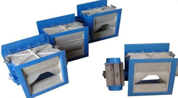
دریچه های فلو کنترل برای قطع جریان خروجی سیلوها و کنترل جریان خروجی آنها که حاوی مواد پودری نظیر سیمان و آهک و گچ و خاکستر هستند بکار میروند. دریچه های فلو کنترل عضوی از گروه سیستم انتقال مواد پودری هستند.
توصیه می شود ،قبل از دریچه فلو کنترل از یک دریچه قطع کن تعمیراتی (نظیر اسلاید گیت) استفاده شود تا انجام تعمیرات بدون ایجاد خطر امکانپذیر باشد.
بیشترین میزان جریان خروجی مواد از دریچه فلو کنترل به سایز آن وابسته است.سایزهای 200 و250و 300 و 400و 500 توسط YJK تولید شده اند.
ویژگی ها
دریچه فلو کنترل قابلیت قطع کامل جریان مواد را بدون نشتی دارد .بنابراین با گردش نود درجه ای دیسک میانی ،دریچه کاملا باز یا کاملا بسته می شود.
همچنین با گردش دیسک میانی در زوایایی کمتر قسمتی از جریان مواد از سیلو برقرار یا قطع میگردد.
مجموعه سوییچ نصب شده در وجه دریچه ،اکچویتر یا درایو را در موقعیتهای باز یا بسته یا میانی متوقف میکند.
دیسک میانی و آببندهایش را میتوان به آسانی تعویض نمود.
دیسک میانی دارای شکافی برای خروج مواد است . با چرخش رولر شکاف به میزان 0% الی 100% باز میشود. میزان گردش رولر نشاندهنده این درصد است.
فلو کنترل با سویچ باکسی برای ارسال سیگنال در موقعیتهای انتهایی و میانه ارائه میگردد.
درایوها
- مدل درایو دستی دریچه های فلو کنترل مجهز به اهرم دستی بهمراه دستگیره هستند.رولر میانی علاوه بر توانایی توقف در موقعیت های باز و بسته در یک موقعیت میانی مطلوب می ایستد.
- مدل موتور الکتریکی دریچه های فلو کنترل مجهز به یک گیربکس دو یا سه مرحله ای استاندارد هستند.علاوه بر آن جهت استفاده های خاص امکان تجهیز به درایو اینورتر دار نیز وجود دارد.
- مدل روتاری اکچویتور پنوماتیک دارای شیر کنترلی 3/5 است . با فعال نمودن شستی دستی شیر کنترلی روی اکچویتور می توان دریچه فلو کنترل را بصورت دستی تحریک نمود.
- مدل سیلندر پنوماتیک دریجه فلو کنترل بوسیله سیلندر دو طرفه پنوماتیکی کار میکند که در هر دو موقعیت انتهایی بوسیله شیر 3/5 متوقف می شود.
Short description
Flow control gates are used for shutting off silo discharge spouts and for the controlled discharge of dry pulverized bulk material such as cement, limestone, gypsum and fly ash, from silos. The flow control gate is part of the fluid slide system. It is recommended to install a maintenance cut-off gate (such as slide gate) preceding the flow control gate in order to be able to carry out maintenance works on the flow control gate without hazard. The flow control gate is dust tight cut-off of a silo discharge opening, therefore by rotating the middle disk by 90′; the discharge opening can be fully closed or opened. Furthermore, by rotating the middle disk by a smaller angle, the sectional area of flow is altered, allowing more or less material to flow cut of the silo.
Features
The flow control gate is dust tight cutoff of a silo discharge opening, therefore by rotating the middle disk by 90′; the discharge opening can be fully closed or opened. Furthermore, by rotating the middle disk by a smaller angle, the sectional area of flow is altered, allowing more or less material to flow cut of the silo.
However, each flow control gate is able to govern the flow rate by controlling the rotation of the middle disk. The switch box which is mounted on side of the gate control actuator or drive to stop in open or close or middle positions.
The middle disk and hence its sealing’s can be easily replaced. In CLOSE-position the flow control gate shuts off the material flow. The roller is provided with a discharge opening (control cross-section). Turning the , roller, changes the bore between 0 and 100%. The aperture angle of the roller is indicated as a percentage.
The lower box of the flow control gate is equipped with an air connection socket for the connection of Compressed air with max. 0.8 bar overpressure
Drives
Manual-actuated flow control gates are equipped with a hand lever with catch. In addition to the ‘open’ and ‘closed’ positions, the roller can be arrested in desired intermediate positions
Motor-actuated flow control gates are equipped with standard a two- or three stages spur wheel back-geared motor. Furthermore, for special applications there is the option of mounting variable speed drives
Pneumatic actuated (rotary actuator) is fitted with a 5/3-way valve. The unit on the rotary actuator enables the flow-control gate to be operated manually
Pneumatic piston-actuated flow control gate is operated by means of a double-acting pneumatic cylinder damped in both final positions, containing a special5/3-way valve